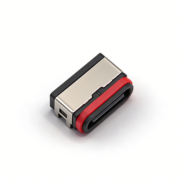
IP67 Waterproof Performance Protection Specification: When assembling the product, the red silicone waterproof ring must be installed strictly in accordance with the drawing requirements to ensure the sealing surface is closely fitted, no misalignment, no excessive extrusion and no falling off. Panel installation must be designed strictly according to the reference dimensions to ensure accurate assembly position. After assembly, a 1-meter water depth 30-minute waterproof sealing test must be conducted to ensure the protection performance meets the standard. It is strictly prohibited to use the product when the waterproof structure is damaged or the assembly is not in place.
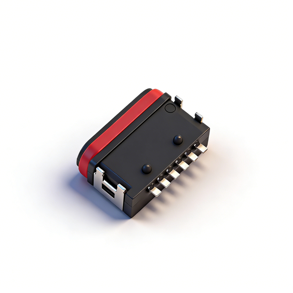
On-board 4-pin Through-hole SMT Mounting and Soldering Specification: PCB pad dimensions, through-hole diameters and positioning hole positions must be designed strictly in accordance with the recommended PCB layout in the drawing. On-board installation must ensure accurate alignment of through-hole positions, ensuring the product is vertically flush with the PCB surface after mounting, no warping and no offset. During SMT mounting, ensure the 4 through-hole pins are accurately aligned with the PCB through-holes, and the surface mount feet are fully attached to the pads to avoid mounting offset, pin bending and pad cold soldering. The reflow soldering peak temperature must be strictly controlled within 260℃±5℃, and the high-temperature residence time shall not exceed 10 seconds to prevent thermal deformation of LCP/PA46 plastic housing, oxidation of stainless steel shell plating and damage to pin contact gold plating, which will affect product performance and waterproof effect.
Special Specification for High Current Use: The rated maximum current of this product is 3.0A. When using, it is necessary to strictly match the corresponding wire diameter conductors and PCB pad design to ensure the current-carrying capacity of the high-current transmission path and avoid overload use. When working with high current for a long time, heat dissipation design must be done to prevent problems such as decreased insulation performance, plastic housing aging and waterproof sealing failure caused by excessive product temperature rise.
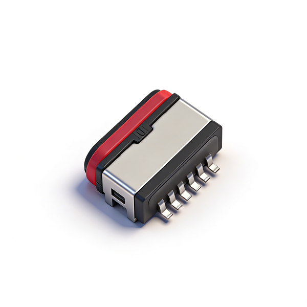
PCB Layout and Equipment Adaptation Requirements: PCB pad dimensions, through-hole diameters and positioning hole positions must be designed strictly in accordance with the product drawing, and sufficient on-board installation space and male plug insertion and extraction operation space must be reserved to avoid physical interference between the product and surrounding electronic components, equipment housing and PCB board. It is recommended to control the PCB layout tolerance within ±0.05mm to ensure the accuracy of on-board through-hole mounting, welding firmness and production yield. The equipment housing opening must strictly match the male plug insertion size and 6.7mm total length size, and the housing thickness design must match the product size to avoid interference damage to the interface during insertion and extraction.
Insertion, Extraction and Use Specification: When inserting and extracting the product, keep the male plug and female socket horizontally aligned and apply force evenly along the axial direction. Violent insertion and extraction, oblique insertion and extraction, shaking insertion and extraction and lateral pulling are prohibited to prevent bending of interface pins, housing cracking, damage to internal contacts and loosening of waterproof structure, which will affect the electrical performance, waterproof performance and service life of the product. It is prohibited to use non-standard, damaged, deformed or foreign matter-containing male plugs for insertion and extraction to prevent damage to the internal structure of the interface and scratching of the contact gold plating.
Tape and Reel Packaging and Automatic Feeding Specification: This product adopts tape and reel packaging, 1000PCS/reel. The carrier tape peeling angle must be controlled within 165°~180°. When feeding with a fully automatic placement machine, strictly control the nozzle position and suction force to avoid product deformation and pin offset caused by excessive nozzle pressure. After the tape is opened, avoid pulling and bending the carrier tape to prevent abnormal peeling force, product falling off and pin damage, which will affect feeding efficiency and accuracy.
Environmental and Storage Requirements: The product must be stored in a dry, dust-free environment without corrosive gases and strong ultraviolet radiation. The storage temperature should be controlled at 5℃~35℃ and the relative humidity ≤75%. Avoid long-term exposure to high temperature, high humidity, acid-base corrosion and salt spray environments to prevent plastic housing aging, silicone waterproof ring loss of toughness, metal plating oxidation and sealing performance attenuation. The product should be used as soon as possible after opening to avoid long-term bare storage affecting the waterproof sealing effect and electrical contact performance.
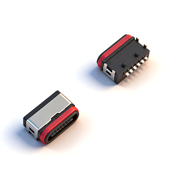
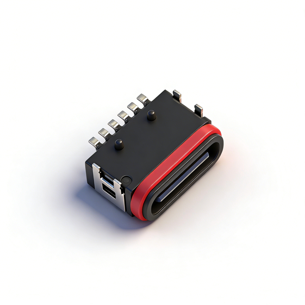
Adaptation and Selection Specification: This product is an IP67 waterproof 6PIN on-board 4-pin through-hole TYPE-C female socket with 6.7mm total length and all-plastic half-pack type. It can only be used with matching standard TYPE-C male plugs. Selection should be based on equipment housing thickness, on-board installation space, waterproof grade and current demand, suitable for basic charging and fast charging protocol identification scenarios. It is prohibited to assemble and use with non-standard, non-customized and size-mismatched male plugs/equipment to prevent problems such as improper interface installation, structural damage, waterproof failure and poor electrical contact.
Transportation and Turnover Specification: During product transportation and production turnover, keep the original packaging intact. Severe impact, extrusion and dropping of the tape reel are prohibited to prevent carrier tape deformation, product falling off, pin bending deformation, shell bump damage and waterproof sealing structure damage. Anti-static protection must be done during turnover to avoid electrostatic breakdown damage to the internal contacts and plating of the interface.