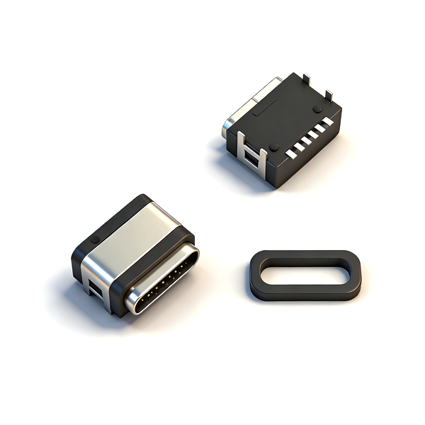
IPX67/IPX8 Waterproof Performance Assembly Specification: The product adopts a double sealing structure of silicone waterproof ring + waterproof resin. When assembling, the silicone waterproof ring must be installed in strict accordance with the drawing requirements, with precise control of 0.1mm compression, to ensure that the waterproof ring is free of damage, distortion and aging, and the sealing surface is tightly fitted without misalignment. The waterproof resin must be evenly filled in the sealing area without bubbles and glue shortage. When installing the PCB board, a gap of 0.1-0.15mm must be strictly reserved to avoid deformation and failure of the waterproof ring caused by extrusion of the PCB board. After assembly, the waterproof sealing test must be carried out. It is strictly prohibited to use products with damaged waterproof structure or inadequate assembly.
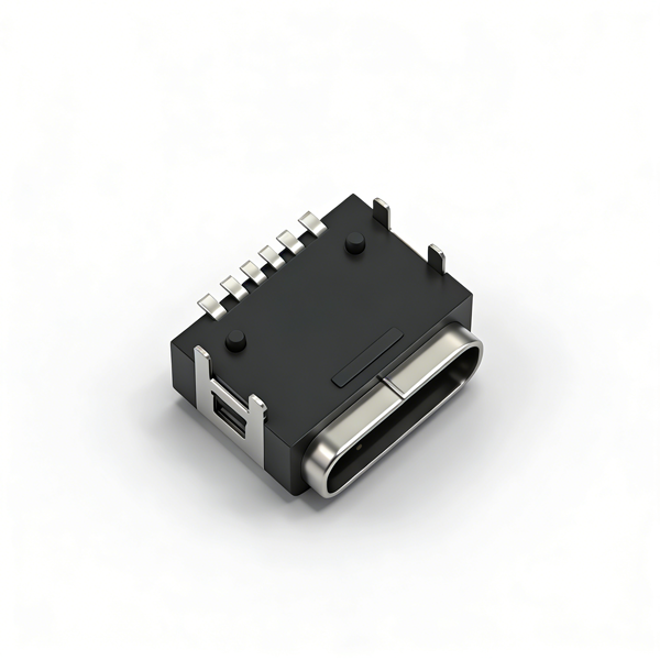
4-Pin Through-Hole Installation & Soldering Process Specification: The PCB pad layout and 4-pin through-hole aperture must be designed in strict accordance with the recommended PCB layout of the drawing to ensure that the product is flush with the PCB surface without warping or offset after installation. During SMT mounting, it is necessary to ensure that the 4 through-hole pins are accurately aligned with the PCB holes, and the SMD pads are fully fitted with the pins to avoid mounting offset, pin bending, cold solder and false solder. The peak temperature of reflow soldering must be strictly controlled within 260℃±5℃, and the high temperature residence time shall not exceed 10 seconds to prevent the PA46/LCP engineering plastic housing from thermal deformation, the stainless steel shell coating from oxidation, and the pin gold plating from damage, which will affect the product performance and waterproof effect.
Rated Current Use Special Specification: The rated maximum current of this product is 3.0A. When using, it is necessary to strictly match the wire with the corresponding wire diameter and the current-carrying design of the PCB pad to ensure sufficient current-carrying capacity of the VBUS and GND current transmission paths, and overload use is strictly prohibited. When working at full load for a long time, a good heat dissipation design must be done to prevent the product from excessive temperature rise, which will lead to the decline of insulation performance, aging of plastic housing, failure of waterproof sealing and other problems. This product is a simplified design specialized for fast charging, without data transmission pins, and cannot be used in scenarios requiring USB data transmission.
PCB Layout & Equipment Adaptation Requirements: The PCB pad size and positioning holes must be designed in strict accordance with the product drawing, and sufficient operating space for plug insertion and extraction must be reserved to avoid physical interference between the product and surrounding components, equipment housing, and PCB board. It is recommended that the unmarked tolerance of PCB layout be controlled within ±0.05mm to ensure the mounting accuracy, welding firmness and production yield of the 4-pin through-hole structure. The opening of the equipment housing must strictly match the insertion size of the Type-C plug and the outline dimension of the product to avoid interference and damage to the interface during plugging and unplugging, and the installation space for the waterproof ring and waterproof resin must be reserved at the same time.
Plugging Operation & Use Specification: When plugging and unplugging the product, the Type-C plug must be axially aligned with the receptacle, and force must be applied evenly along the axial direction. Violent plugging, oblique plugging, shaking plugging, and lateral bending are strictly prohibited to prevent interface pin bending, full-plastic shell deformation, internal contact damage, and waterproof structure loosening, so as to avoid affecting the electrical performance, waterproof performance and service life of the product. It is forbidden to use non-standard, deformed, damaged plugs or plugs with foreign objects for plugging, to prevent damage to the internal structure of the interface and scratching of the gold plating layer of the contacts.
C2680 Brass Alloy Contact Use Specification: The contact terminals of the product are made of C2680 brass alloy, which has excellent conductivity and processability. During use, foreign object insertion into the interface and long-term overload plugging are strictly prohibited to avoid contact deformation, elasticity failure and poor contact. During long-term use, it is necessary to regularly clean the dust and foreign objects inside the interface to avoid contact oxidation and increased contact resistance, which will affect the fast charging protocol communication and charging performance.
Tape & Reel Packaging & Automatic Feeding Specification: This product is packaged in tape and reel, 600PCS per reel. The peeling angle of the carrier tape must be controlled within the range of 165°-180°. When feeding with a fully automatic mounter, the nozzle position and suction must be strictly controlled to avoid pin offset and full-plastic shell deformation caused by excessive nozzle pressure. After the tape is opened, it is necessary to avoid pulling and bending the carrier tape to prevent abnormal peeling force, product falling off and pin damage, which will affect the feeding efficiency and mounting accuracy.
Storage & Environmental Use Specification: The product must be stored in a dry, dust-free environment without corrosive gas and strong ultraviolet radiation. The storage temperature is controlled at 5℃~35℃, and the relative humidity is ≤75%. Avoid long-term exposure to high temperature, high humidity, acid-base corrosion and salt spray environment to prevent aging of PA46/LCP plastic housing, loss of elasticity of silicone waterproof ring, oxidation of metal coating and attenuation of sealing performance. The product should be used as soon as possible after opening, to avoid long-term exposed storage affecting the waterproof sealing effect and electrical contact performance.
Transportation & Turnover Specification: During the transportation and production turnover of the product, the original packaging must be kept intact. Severe impact, extrusion and falling of the tape reel are prohibited to prevent carrier tape deformation, product falling off, pin bending deformation, full-plastic shell bump damage and waterproof sealing structure damage. Anti-static protection must be done throughout the turnover process to avoid electrostatic breakdown damage to the internal contacts and gold plating of the interface, which will affect the stability of fast charging protocol communication.